Shadow Mapping
Shadow mapping is a technique to simulate shadows. The basic version could create hard shadows. The advanced versions could even create soft shadows, and look very real. This article walks through some basics, and the demo comes here.
Basics
Shadowmap builds on top of projections, so let’s briefly review them.
Perspective Projection
Perspective projection maps a view frustum to unit cube (or NDC, figure). If we describe the view frustum with $x_{-1}$, $x_1$, $y_{-1}$, $y_1$, $z_{-1}$, $z_1$, then the matrix could be written as
\[\begin{pmatrix} -\frac{2z_{-1}}{x_1 - x_{-1}} & 0 & \frac{x_1 + x_{-1}}{x_1 - x_{-1}} & 0 \\ 0 & -\frac{2z_{-1}}{y_1 - y_{-1}} & \frac{y_1 + y_{-1}}{y_1 - y_{-1}} & 0 \\ 0 & 0 & -\frac{z_1 + z_{-1}}{z_1 - z_{-1}} & \frac{2z_1 z_{-1}}{z_1 - z_{-1}} \\ 0 & 0 & -1 & 0 \end{pmatrix}\]Notice that $0 < z_{-1} < z_1$, because the camera looks at $-z$ by convention.
Orthogonal Projection
Orthogonal projection maps a cuboid to unit cube (or NDC, figure). If we describe the cuboid with $x_{-1}$, $x_1$, $y_{-1}$, $y_1$, $z_{-1}$, $z_1$, then the matrix could be written as
\[\begin{pmatrix} \frac{2}{x_1 - x_{-1}} & 0 & 0 & -\frac{x_1 + x_{-1}}{x_1 - x_{-1}} \\ 0 & \frac{2}{y_1 - y_{-1}} & 0 & -\frac{y_1 + y_{-1}}{y_1 - y_{-1}} \\ 0 & 0 & \frac{2}{z_1 - z_{-1}} & -\frac{z_1 + z_{-1}}{z_1 - z_{-1}} \\ 0 & 0 & 0 & 1 \end{pmatrix}\]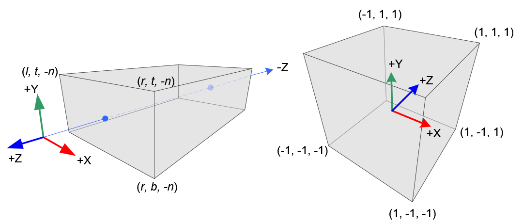
The convention of $0 < z_{-1} < z_1$ also applies here.
Model, View, Projection
\[x' = P \cdot V \cdot M \cdot x\]$M$ puts $x$ in the world coordinate; it’s just a combination of translation and rotation. $V$ puts $Mx$ in the camera coordinate; besides translation and rotation, it also applies a reflection, so that the camera looks at $-z$ direction. $P$ maps $VMx$ to a unit cube; the points with smaller $z$ will occlude those with larger ones.
GLM
GLM (and the js version here) provides helper functions to create the matrices we need. For example, if we want to put the model at $(0, 0, 2)$, we could simply say
var M = glm.translate(glm.mat4(0), glm.vec4(0, 0, 2, 1));
One thing to take in mind is that the order of the GLM transform functions that are applied is different from the matrix order. In math, the transform can be represented as left multiplication of a matrix. For example, if we want to rotate (R) then translate (T), then the combinition would be $TR$. However, when it’s expressed in GLM, it will be
glm.rotate(glm.translate(...), ...);
A nice explanation of lookAt can be found here. The main confusion to me came from center and up. center is a reference point in the direction that the eye (or camera) is looking at. Whatever point on this direction could be chosen; the implementation will compute the normalized direction anyway. The choice of up is also not unique. It doesn’t have to be perpendicular to the direction of your sight; the implementation will find a true up direction perpendicular to the sight. The purpose of passing in this argument is just to prevent showing the world up side down.
Therefore, if we want to put a camera at original, looking at $z$ direction, we could find whatever point as reference point (e.g. glm.vec3(0, 0, 1)), pick whatever direction that is up (e.g. glm.vec3(0, 1, 0)), and say
var V = glm.lookAt(glm.vec3(0), glm.vec3(0, 0, 1), glm.vec3(0, 1, 0));
After applying V, the transform would put the center of the world at $-z$ axis, with the camera looking towards it.
For perspective projection, GLM only provides function for symetric perspective-view frustum (i.e. $x_{-1} = -x_1$, $y_{-1} = -y_1$). The parameters include
fovy: see figure; it’s in radian.aspect:w/h, aka $(x_1 - x_{-1}) / (y_1 - y_{-1})$.zNear: $-z_{-1}$.zFar: $-z_1$.
You may want to pick the proper parameters, so the object is not clipped.
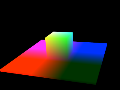
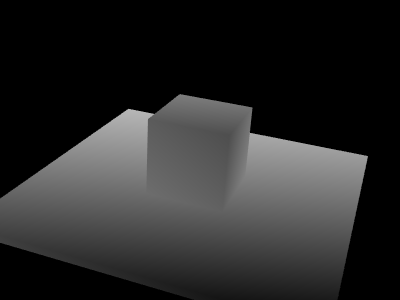
Basic Scene
To illustrate the shadow mapping, let’s draw a basic scene first: put a small cube on a flat cuboid.
const center = glm.vec3(0, 0, 16);
const modelMatrix =
    glm.rotate(
        glm.translate(glm.mat4(1), center),
        /* angle= */ glm.radians(20),
        /* axis= */ glm.vec3(-1, -1, 0));
const viewMatrix =
    glm.lookAt(
        /* eye= */ glm.vec3(0, 0, 0), center,
        /* up= */ glm.vec3(0, 1, 0));
const projMatrix =
    glm.perspective(
        /* fovy= */ glm.radians(30),
        /* aspect= */ 4./3,
        /* zNear= */ 10,
        /* zFar= */ 30);
Shadow Mapping
The basic shadow mapping consists of two passes: the depth pass and the shadow pass. In the depth pass, we compute the depth map of the scene in the view of light, and in the shadow pass, we do a depth test to see if the point is in shadow or not.
Depth Pass
To compute the depth in the view of light, the logic of computing model, view, projection matrices could be reused. For example, if we want to put a light bulb at (0, 10, 26), it’s equivalent to putting a pinhole camera there. If it were directional light, the projection matrix also needs to be replaced with orthogonal projection matrix.
const viewMatrix =
    glm.lookAt(
        /* eye= */ glm.vec3(0, 10, 26), center,
        /* up= */ glm.vec3(0, 1, 0));
Vertex shader
attribute vec3 aPos;
uniform mat4 uLightMVP;

void main() {
  gl_Position = uLightMVP * vec4(aPos, 1);
}
Fragment shader
precision mediump float;

void main() {
  gl_FragColor = vec4(gl_FragCoord.zzz, 1);
}
Take in mind that gl_FragCoord.z is in the range of [0, 1]. Later when we compare fragmentLightDist and occluderLightDist, we must make sure they are in the same measure space.
Shadow Pass
In the shadow pass, we need to do the depth test, and give the fragments in the shadow less intensity. We would still render the scene in the perspective of the camera. That being said, for each fragment $x$, we will compute its gl_Position in the unit cube given the view matrix $V_c$ and the projection matrix $P_c$.
Now let’s do the depth test. On one hand, for a light source with view matrix $V_l$ and projection matrix $P_l$, its position in the eye of light is
\[x_l = P_l V_l M x\]On the other hand, the first occluder between this fragment and the light is encoded in the depth map computed in the previous pass. Let’s say the occluder is $y$; in the previous pass we know
\[y_l = P_l V_l M y\]and have put them in the depth map $Y_l$. If we say $y_l=(y_l^1, y_l^2, y_l^3, 1)^T$, then we can easily look up the depth $y_l^3$ by reading $Y_l[y_l^1][y_l^2]$. If we put $Y_l$ in a frame buffer, and bind it with a texture, we can easily sample $(y_l^1, y_l^2)$ from it. As $x_l$ and $y_l$ are on the same ray of light, $(x_l^1, x_l^2) = (y_l^1, y_l^2)$. Therefore, the depth of the cloest occluder to the light can also be looked up via $Y_l[x_l^1][x_l^2]$.
To put it in shaders, the vertex shader needs to compute $x_c$ and $x_l$ for each $x$.
const mat4 kBias = mat4(
    vec4(0.5, 0.0, 0.0, 0.0),
    vec4(0.0, 0.5, 0.0, 0.0),
    vec4(0.0, 0.0, 0.5, 0.0),
    vec4(0.5, 0.5, 0.5, 1.0));

attribute vec4 aPos;
uniform mat4 uCameraMVP;
uniform mat4 uLightMVP;
varying vec4 vLightCoord;

void main() {
  gl_Position = uCameraMVP * aPos;
  vLightCoord = kBias * uLightMVP * aPos;
}
The fragment shader needs to do the depth test and add shadow for the occluded fragments.
uniform sampler2D uDepthMap;
varying vec4 vLightCoord;

void main() {
  vec4 lightCoord = vLightCoord / vLightCoord.w;
  float fragmentLightDist = lightCoord.z;
  float occluderLightDist = texture2D(uDepthMap, lightCoord.xy).z;
  if (fragmentLightDist > occluderLightDist) {
    // The fragment is behind the occlucer, so it's in the shadow.
    ...
  }
}
Notice that we need to apply a kBias besides uLightMVP. That’s for ease of texture sampling, and also guarantees that the depth range is the same as was computed before in the depth pass. By doing this, we guarantee that lightCoord.xyz, after normalizing the w component, are all within the range of [0, 1].
Depth Map as Texture
This part is WebGL/OpenGL specific. We need to render the depth map as texture, and pass it to the shadow pass. By default, WebGL will render to the canvas, unless we set our own frame buffer. Here’s one caveat for frame buffer: it does not have depth attachment by default, so the depth test won’t work. We could get some faces missing in the framebuffer, while in the canvas everything works fine. Therefore, we need to add the following
const renderbuffer = gl.createRenderbuffer();
gl.bindRenderbuffer(gl.RENDERBUFFER, renderbuffer);
gl.renderbufferStorage(
    gl.RENDERBUFFER, gl.DEPTH_COMPONENT16, width, height);

const framebuffer = gl.createFramebuffer();
gl.bindFramebuffer(gl.FRAMEBUFFER, framebuffer);
gl.framebufferRenderbuffer(
    gl.FRAMEBUFFER, gl.DEPTH_ATTACHMENT, gl.RENDERBUFFER, renderbuffer);
Shadow Acne
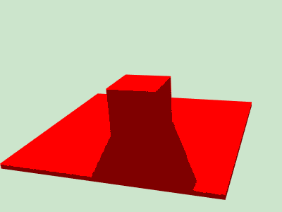
If we simply check the fragment-light distance vs the occluder-light distance, we would get something like this

It’s known as shadow acne. It happens because the pre-computed depth map is descrete, and there will be some belt regions where the fragment-light distance is farther in the descrete space, but the actual distance in the continuous space is closer. A simple workaround is to apply a bias on distance to digest the descrete error.
if (fragmentLightDist > occluderLightDist + kEps) {
  // Apply kEps' bias to digest the error.
}